IBM System/23 Datamaster: Difference between revisions
mNo edit summary |
No edit summary |
||
| Line 1: | Line 1: | ||
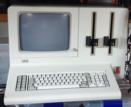
The IBM System/23 Datamaster is the first IBM computer to be based upon an Intel CPU and the only known IBM computer to feature an 8-bit microprocessor. Along with the [[Displaywriter]], is one of the few EBCDIC |
The IBM System/23 Datamaster is the first IBM computer to be based upon an Intel CPU and the only known IBM computer to feature an 8-bit microprocessor. Along with the [[Displaywriter]], is one of the few EBCDIC microcomputers ever made. Development of the hardware began in 1978 and was ready to roll out by late 1979, but due to the late decision to make its BASIC compatible with the one from the System/34 the software delayed its release to July 1981, just one month before the [[IBM 5150 Personal Computer]]. As a result, it was a commercial failure and sold very poorly. While IBM engineers decided to use industry standard components instead of their own SLT family, all references were ofuscated by remarking them with its IBM internal catalog number; this fact difficults enormously their repair and most units are in a state of decay. |
||
{| style="float:right;margin:10px;border:1px solid black" |
{| style="float:right;margin:10px;border:1px solid black" |
||
Revision as of 10:53, 23 December 2024
The IBM System/23 Datamaster is the first IBM computer to be based upon an Intel CPU and the only known IBM computer to feature an 8-bit microprocessor. Along with the Displaywriter, is one of the few EBCDIC microcomputers ever made. Development of the hardware began in 1978 and was ready to roll out by late 1979, but due to the late decision to make its BASIC compatible with the one from the System/34 the software delayed its release to July 1981, just one month before the IBM 5150 Personal Computer. As a result, it was a commercial failure and sold very poorly. While IBM engineers decided to use industry standard components instead of their own SLT family, all references were ofuscated by remarking them with its IBM internal catalog number; this fact difficults enormously their repair and most units are in a state of decay.
| Manufacturer | IBM |
| Models | 5322, 5324 |
| CPU | Intel 8085@6.14MHz (effective 3.07MHz) |
| DMA | Intel 8257 |
| CRTC | Intel 8275 |
| Display | 80x24 characters, MDA-like |
| FDC | NEC 765 |
| RAM | 32KB/64KB/96KB/128KB |
| ROM | 128KB-272KB |
Historical Signifiance
Commercial Failure
The scarcity of those systems is the result of high prices (it was marketed at USD9000 at the time), delayed availability, poor marketing and the release of in-house competing systems such as the Displaywriter and the PC. This made the computer fail to be adopted by the marked, which had a plaethora of competing systems at much more competitive price and performance. Therefore the System/23 quickly became a niche in the marked and was soon forgotten as the technology improved quickly in the mid-80s.
Influence over the 5120
The long development time of the IBM Datamaster made its case a model for the IBM 5120, which adopted a variant. While it is acknowledged that both units have related cases, it is usually wrongly stated that the 5120 influenced the System/23 where in reality it was the Datamaster that influenced the 5120.
Usage of standard parts
The IBM Datamaster is the first IBM computer to rely on then industry-standard components including microprocessor, memories, peripheral devices and logic integrated circuits. This aproach would be reused in the Displaywriter (which has a mix of both standard components and IBM SLTs) and later developments, such as the PC family of computers. However, the references were changed to avoid third parties to tamper with the machine.
Creation of the IBM PC
It is often said that the IBM had a rushed development of the PC with a single year in development. Whereas the statement is partially true, it is also forgotten how close both systems are and how the same engineers that worked in the Datamaster later worked in the PC, bringing the required expertise. Also, the chosen CPU was the Intel 8088 due of its similarity hardware-wise with the Intel 8085 and this way most of the peripherals were maintained in the transition from the Datamaster. The character set and its format were also brought from the System/23 to the 5150. Also, the expansion bus is nearly untouched in that evolution. Finally, from pictures of early prototypes it can be seen that the power connectors were the same as the one in the Datamaster. As a conclusion, it might be stated that the early life of the IBM PC started as modifications on the Datamaster.
Hardware Description
Microprocessor and timing
The CPU selected to serve as the core of the system was the Intel 8085. However, as the component references were ofuscated identifying the CPU was not a straightforward task. It was hinted that the component with reference 4178015 could be the part. To confirm the true identity of the integrated circuit, an exchange with a legit 8085 was done: the remarked part went into a P2 CPU board and the P2 CPU went in place of the unknown component. The test went successfully and the cross reference was proved as fact.[1]

The computer has no specific reset circuit like other computers but it is just triggered by the "Power_Good" signal from the power supply unit.
Regarding the system clock, it is derivated from a 18.432MHz square wave oscillator which is then divided by three to feed the microprocessor with a 6.14MHz signal.
ROM Operating System
| ROS Code | ROM Reference |
|---|---|
| 02 | 4481186 |
| 09 | 8493747 |
| 0A | 8519402 |
| 0B | 8519404 |
| 0C | 8519403 |
| 0D | 8519405 |
| 10 | 8519411 |
| 11 | 8519407 |
| 12 | 8519408 |
| 13 | 8519414 |
| 14 | 8519406 |
| 15 | 8519416 |
| 16 | 8519409 |
| 17 | 8519410 |
| 18 | 8519417 |
| 19 | 8519411 |
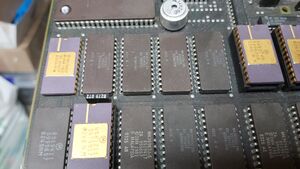
The ROM Operating System or simply ROS is the firmware of the System/23. It consists in a set of sixteen ROMs of 8KB each, for a total of 128KB, although the service manual states 112KB which means they did not count the non-paged ROM memory[2]. Each ROS ROM has a unique diagnostics identification code, which is determined by the outputs of two 74LS138 3:8 decoders. ROMs 02h and 09h are fixed in the memory map, where the rest are paged in the memory range 4000h-7FFFh. ROMs 0Eh and 0Fh are not present but the logic to select them is implemented even if there is no place to place them in the board; still, with an appropriate ROM adapter their space could be enabled to inject code into the system.
ROMs paged 0-7 are present in the board while ROMs paged 8-15 are expected to be provided by expansion cards on their corresponding slots. Therefore, the maximum theoretical ROM capacity for the Datamaster consists of 272KB if the 0Eh-0Fh gap and pages 8-15 are used.
Regarding the diagnostics, every single ROS image contains its own reference inside the code[1]. It is still not known at the moment of this writing but it is supposed to be part of the verification algorithm used by procedure PID 1200. Other important aspects to have in mind during the checks are that if the ROM identifier is inverted the memory is faulty. In case it is underlined, usually means that it is not present or detected. Usual causes for this fault are either power supply issues or memory select signals.
Regarding the memories as components, they usually come as Mostek MK36000 or Motorola 68366 and has been reported that in early units the components were Motorola 68766 EPROMs due to delays in supply lines[3]. Nowadays, the Mostek memories are prone to fail and are one of the major causes of failure of this kind of computer. The issue can be solved easily with adapters, in case that the appropriate firmware is provided.
RAM Memory
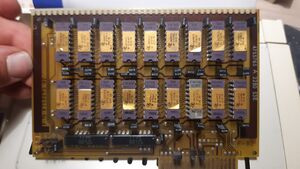
RAM in the Datamaster is completely contained in one to two boards complementary to the motherboard and are attached through a card-edge connector of 36 pins each. This facilitates the removal and placement of memory cards into the system and grants the possibility of fast repair and extension of the computer. There are two memory slots, and at the same time official memory boards were produced in two sizes: 32KB and 64KB respectively. This led to five possible official configurations.[4]
Still, it is known that the official maximum of 128KB is just the maximum for the earlier models of 5322, as later revisions could address up to 256KB by configuring some jumpers in the motherboard. This is possible as the bank control register is implemented with a 74LS670, which is 4 bits wide, giving 16 pages of 16KB each. Additionally, there is a non-banked page which is used among other things as the display memory. For this reason the actual theorical maximum memory for a System/23 is 272KB. Still, it has been hinted that some clones of the system exist and that those expand the width of the page register to eight bits, giving the theorical maximum to 4112KB to them.
The memory boards contain one or two TMS4132 arrays of 9 memories each[1]. Having nine units per bank allows them to have a data byte width of data plus a ninth bit for parity. Both because of the rareness of the format of the TMS4132 and the replacement of the official reference led for years to believe that IBM soldered the memories in piggyback to cope with failure rates when in reality it was a feat of Texas instruments to sell them directly soldered after manufacture of both dies. This kind of memory contains a 16KB bank per package and both packages have a slight difference of the pinout to not have conflict with /CAS and /RAS.[1]
| Feature board | Option board | Total |
|---|---|---|
| 32KB | None | 32KB |
| 32KB | 32KB | 64KB |
| 64KB | None | 64KB |
| 64KB | 32KB | 96KB |
| 64KB | 64KB | 128KB |
Memory is subject to many diagnostics tests, some of which are considered critical and could prevent the system from successfully IPL, giving the impression of a completely dead computer whereas only the memory could be failing. It has also been tested that the computer won't boot if no memory board is present at the "feature" socket.
A common cause of failure for this board and subsequently the whole computer is by having faulty capacitors in shortcircuit in the RAM power supply lines[1]. By simply removing them the issue is solved. In case of 4132 failure, each 4132 upper and lower packages must be separated in order to run the tests.
Diagnostics port
The System/23 has a dedicated diagnostics port[5]. It is controlled by a single 8255 by using its port B, whereas ports A and C have no relation in function; for this reason it is deduced that port B is working in mode 0, without handshaking of any sort. This fact is confirmed by the eight data lines which conform the data port being directly connected only to port B and the remaining four signals are for supplying power to the probes.[1]
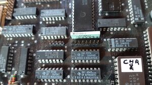
After finding the pinout of the diagnostics port a simple probe containing a led per data line was built, and it showed a count when booting. Removing the RAM board(s) caused the count to stop at "00000100" (4 in decimal), which corresponds to a memory check test procedure of PID 1200. With those facts it was deduced that the port was outputting a two-digit hex code which was written just before the start of a test routine and would stop when the error was considered critical.[1]
For most cases it is not necessary having the probe, as the same values that are outputted through the service port are also written in the video memory, displaying the passed tests and the errors encountered. However, as the same tests that check the video display controller are the same routines that initialize it, all the tests made before the initialization cannot be seen in the screen until passed. In case some of them failed the screen would not be initialized and therefore the results wouln't be seen. For this reason the probe is still needed.[1]
Keyboard
The computer presents itself with a pre-Model F keyboard with 83 keys. Internally, it used the very same components than the keyboard of the IBM PC would later. The only difference between them is that the PC uses a serial interface to communicate the peripheral with the computer and the Datamaster has a parallel interface. This change also implies that the code in the 8048 microcontroller both carry is different. For this reason this was also one of the most common causes of not repairable failures.
Expansion ports
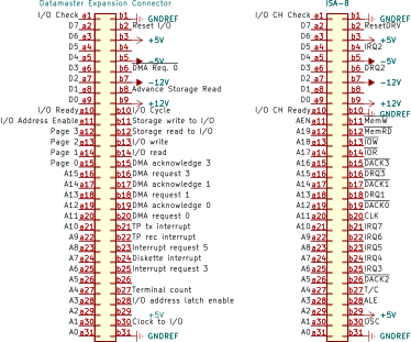
The Datamaster has three expansion ports located at the rear of the system. It is important to notice that when the PC was developed most of the pins were left in place and, contrary to the popular belief, one is not the mirrored image of the other.[6]
Power Supply Unit
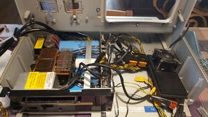
The power supply of the computer is a heavy block which consists in a linear supply that outputs +5V, +12V, +24V, -5V and -12V[7]. Its connector is a 12-pin molex structured in three columns and four rows. Other than the voltages, it also provides with a "power good" signal as posterior IBM computers would, such as the IBM PC. The first IBM PC prototype used the same connector and possibly the same pinout. Adapting an ATX supply to feed the main board is possible and relatively easy to do (actually, it is recommendable when testing the system in a bench). When the connector transitioned to the PC it was linealized but maintained all contacts present in the Datamaster power supply connector, including the key pin (N.C.). The change might have been motivated to reduce friction when attaching/deattaching the cord.[1]
Logical Description
Simplified Memory Map
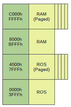
The IBM System/23 divides its 64KB of addressable space in four segments of 16KB each. All even segments are fixed into the memory map but all the odds are paged and can support up to 16 pages each. The first half portion of the map corresponds to ROM while the last half of it is mapped to RAM[8].
Pagination is achieved thanks to four registers mapped 20h-23h at the I/O space. From those, one determines the ROS page being read, another is used by the DMA mechanism and the other two are used by the CPU access to RAM (for reading and writing, respectively). The widths of each register is four bits, therefore allowing the maximum of sixteen pages. From those, the first eight are expected to be in the board while the remaining are expected to be provided by each expansion card added.
Video memory seems to be placed at address 8000h (to be confirmed).
I/O Ports
The Datamaster has a rich set of Intel peripherals which consist of a 8251 USART, 8253 PIT, three 8255 PPI, 8257 DMA, 8259 PIC and 8279 CRTC. All of them, including other devices are accessed the following ports[1]:
| Ports | Device |
|---|---|
| 00h-0Fh | DMA |
| 20h-23h | Page registers |
| 24h-27h | PIT |
| 28h-2Bh | PIC |
| 2Ch-2Fh | 8255#3 |
| 40h-43h | Service port |
| 44h-47h | CRTC |
| 48h-4Bh | USART |
| 4Ch-4Fh | Keyboard port |
Timers
Having a 8253 PIT the computer has access to three independent programmable timers.
| Timer | Function |
|---|---|
| Timer 0 | Baud rate generator for 8251 USART |
| Timer 1 | Beeper |
| Timer 2 | 8085 interrupt RST7.5 |
Diagnostics
The System/23 Datamaster implements a set of self-test routines identified as "PID-1200". With them it tests the CPU, the memory and the different peripherals of the computer. Usually the results of the tests are written to the screen at start-up but if an error occurs before the initialization of the screen a probe is needed. The tests are identified by an hexadecimal value and can be presented unstyled, underlined or inverted. In the case of being underlined it means that the feature tested wasn't found by the system, whereas if it is inverted it has been detected but was tested and found faulty. If the text is left unstyled, it means the test passed. The test routines and their tested areas are the following[9]:
| Test | Description | Notes |
|---|---|---|
| 01 | CPU and data bus | |
| 02 | First unpaged ROS ROM | This is the ROM at 0000h |
| 03 | Reserved | Unknown |
| 04 | RAM | Test for the first 64KB |
| 05-07 | CRTC | Initialization and test; any error in this step or earlier requires a probe |
| 08 | Page registers | For CPU access, ROM only |
| 09 | Unpaged ROS ROM | The second part of the unpaged segment |
| 10-19 | Paged ROS ROMs in the motherboard | |
| 1A-29 | ROS Extensions | Test for ROMs in expansion slots |
| 2A-30 | RAM | Test for the last 64KB |
| 31 | Paging Register | For CPU access RAM only |
| 32 | Paging register | For DMA access |
| 33 | PIC | Interrupt controller initialization and test |
| 34 | PIT | Interval timer initialization and test |
| 35 | Keyboard | Tests if communication with the keyboard controller is successful |
| 36 | Printer | Checks if there is a printer attached to the computer |
| 37 | Printer diagnose | Sends a diagnose command to the printer and waits the response |
| 38 | Floppy disk drive controller | Checks if there is a FDC card in the expansion slots and if it is functional |
| 39 | +24V | Tests internal line of +24V supplied to the drives |
| 3A | Secondary printer | Checks if there is a printer control card in the expansion slot and checks if there is a printer attached to it |
| 3B | Secondary printer diagnose | If the previous test is successful, Sends a diagnose command to the secondary printer and waits the response |
| 3C | Internal wrap of serial interface adapter | Unknown |
| 3D | Disk unit | Checks if there is a 5247 external disk unit connected |
| 3E | Disk unit ready | In the previous test is successful, wait until the drive is ready |
| FD | System diskette installation | Unknown |
Note that in case a ROM is unselected or unpowered it will mark its test as "missing". ROMs 0E and 0F aren't present on the board and therefore its tests will always result with a "missing" status.[1]
Gallery
Units in collection
| Inventory ID | Model | Submodel | Comments |
|---|---|---|---|
| 22 | 5322 | 124 | Fitted with 64KB RAM + 2 x 8" floppy drives |
See also
IBM System/23 Datamaster Resources
References
- ↑ 1.00 1.01 1.02 1.03 1.04 1.05 1.06 1.07 1.08 1.09 1.10 Own research
- ↑ SY34-0171-0 IBM 5322 Computer Service Manual, page 74
- ↑ https://forum.vcfed.org/index.php?threads/searching-for-ibm-s-23-datamaster-users.1241962/post-1386460
- ↑ 4.0 4.1 SY34-0171-0 IBM 5322 Computer Service Manual, page 36
- ↑ SY34-0171-0 IBM 5322 Computer Service Manual, page 37
- ↑ https://forum.vcfed.org/index.php?threads/system-23-datamaster-i-o-slots.1248011/
- ↑ SY34-0171-0 IBM 5322 Computer Service Manual, page 30
- ↑ SY34-0171-0 IBM 5322 Computer Service Manual, page 78
- ↑ 6841631 System/23 Diagnostic User Guide, page 87
